

Understanding Basics and Application of GD&T Symbols - Machining components very precisely is not an easy and you need to spend extra money in machine shop.

And Engineers started to use Geometric Dimensioning and Tolerancing in the Engineering Drawing to tell the Machinist. Hey look this is the actual dimension and you are allowed to attain the finished component dimension plus or minus tolerance value.
This makes job easy for Machinist to work with machines and make cost effective products.
Interchangeability of manufactured parts is a critical element of present day production. The production of closely mating parts, although theoretically possible, is economically unfeasible. For this reason, the engineer, designer or drafter specifies an allowable deviation (tolerance) between decimal limits.
The definition of a Tolerance, per ASME Y14.5.5M-1994, is the total amount a specific dimension is permitted to vary. For instance, a dimension shown as 1.498” to 1.502” means that it may be 1.498” or 1.502” or anywhere between these dimensions. Since greater accuracy costs money, you would not callout the tightest possible tolerance, but instead would callout as generous a tolerance as possible.
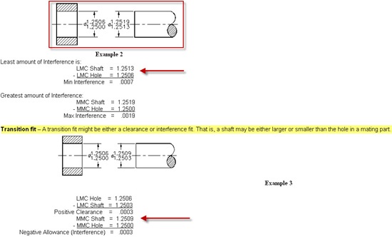
Fig: How to calculate Clearance Fit, Interference fit, Transition fit,Basic Hole and Shaft System
From MAE LABS, Engineers can quickly understand use of GD&T Basics,Types of Fits,Definition of Running and Sliding fits (RC1-RC9),Clearance locational fits (LC1-LC11),Transition locational fits (LT1-LT6),Interference locational fits (LN1-LN3),Force and shrinks fits (FN1-FN5)
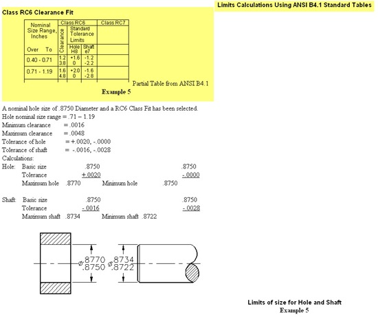
Fig: Explanation on Limits Calculations Using ANSI B4.1 Standard Tables
Important Terms Definition:
Maximum Material Condition (MMC) – Is the condition where a feature of a finished part contains the maximum amount of material. That is, the largest shaft or smallest hole. See Example 1.
Least Material Condition (LMC) - Is the condition where a feature of a finished part contains the least amount of material. That is, the smallest shaft or the largest hole. See Example 1.
Nominal Size – Approximate size used for the purpose of identification such as stock material.
Basic Size – Is the theoretical exact size from which limits of size are determined by the application of allowances and tolerances.
Tolerance – The total amount by which a given dimension may vary or the difference between the limits.
Limits – The extreme maximum and minimum sizes specified by a toleranced dimension.
This is the real good learning source for Design Engineers,Quality Engineers to learn and understand basics of GD&T.


0 Comments: